The patented tekMass TMS Series is designed for bi-directional mass or NTP corrected volumetric flow measurement of pure or mixed gases.
tekMass has the largest flow ranges available from 0.35 kg/h to over 12 million kg/h (1.2 lb/h to > 26 million lb/h). It is accurate to < ± 1% of reading, with traceability to USA NIST and other international standards. However, as with all flow sensors, in order to achieve such performance, users should be aware of the principle of operation, some of the common challenges and how to avoid them.
How tekMass Operates
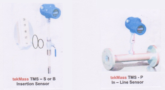
tekMass embodies 2 high stability thermal sensors, either for insertion into a pipe or duct, under pressure if necessary. Alternatively, it may be supplied as an in-line sensor, complete with spool piece and process flanged connections.
One sensor is heated and the other is a reference. The reference sensor resistance is accurately maintained and the power required to provide a constant temperature between the heated sensor and the reference sensor is a measurement of the mass flow of the gas flowing past the 2 sensors.
tekMass is normally calibrated on air, or the application gas, against an internationally recognized primary standard. On some occasions, for example exotic or mixed gases, the calibrated air mass flow can be corrected by determining the square root of the product of the thermal conductivity and density of the particular application gas. A customized NIST traceable Calibration Certificate is provided for each tekMass, expressed in either volumetric flow corrected to normal NTP conditions or in mass flow units.
Some Important Challenges
• Sizing the tekMass
It is important to state the type of gas such that the thermal conductivity and specific heat can be determined, as well as the operational density (temperature and pressure range).
The tekMass data sheet provides recommended flow rates based on air at NTP (20º C, 1.013 bar absolute). As the thermal conductivity and of a gas increases then the tekMass signal increases by square root law over the tables on air flow range at NTP. That means the equivalent air flow range at NTP is less. The specific heat also plays a non-linear role in determination of equivalent air flow at NTP
As a gas pressure increases, the gas molecules become packed more closely together, meaning its density will increase. Accordingly, the tekMass signal increases also by square root law over the tables on air flow range at NTP. Again, the equivalent air flow range at NTP is less
To avoid the resultant decreased sensitivity caused by variation in specific heat, higher thermal conductivity of gases and/or higher gas pressures, flow rates or their calculated equivalents greater than those stated in the tekMass data sheet are not recommended. Generally, it is also not recommended to use thermal gas flow sensors greater than 10 bar g (145 psig). In all these cases a tekVorx vortex sensor or tekProbe multivariable averaging Pitot should be used. Consult tekflo sensors for expert advice.
• Moisture in the Gas
Condensed moisture in the gas contacting the thermal sensors will suddenly result in increased thermal conductivity. The raw signal will become ‘noisy’ with increased spikes, resulting in decreased accuracy and repeatability. Damping the signal does not provide an accurate result, since the noisy, spikey signal is very irregular. Damping the signal does not result in accurate averaging.
One way of obviating the problem requires installing a moisture separator in the pipeline upstream of the tekMass. The straight pipe runs should be a minimum 15 diameters upstream after the moisture separator and 5 downstream before a bend. When the moisture laden gas enters the relatively large separator there is a localized reduction in its velocity, besides a change in direction. The moisture falls to the bottom of the separator tank, leaving the resultant dry gas to flow upwards and out.
A less expensive and simper approach is to place the tekMass at typically 45 degrees from vertical in a horizontal pipe. The condensed moisture then drops away from the tekMass.
Should there be extreme amounts of moisture in the gas, a tekVorx vortex sensor or tekProbe multivariable averaging Pitot should be considered. Consult tekflo sensors for expert advice.
• Solids Build-Up
In most cases, when solids build on the thermal sensors the effect is to reduce the thermal conductivity. This causes the tekMass to read lower and reduce response time. There are some solids of high thermal conductivity which have the opposite effect, but these are in a significant minority.
The easiest solution is to use a retractable insertion tekMass, complete with locking gland and ball valve, through which the tekMass may be withdrawn under pressure for periodical cleaning.
Should there be extreme amounts of solids in the gas, a tekVorx vortex sensor or tekProbe multivariable averaging Pitot should be considered. Consult tekflo sensors for expert advice.
• On-Site Calibration Verification
tekMass is equipped with advanced calibration verification, which is on-site traceable to USA NIST and other international standards, When the tekMass microprocessor is turned on a self-check analysis is performed automatically. This calibration check may also be performed when desired.
If any change to the original calibration occurs, for whatever reason, a self-check interface will be displayed for 1 – 2 seconds. A display will change from OK to ERR, meaning error. The menu can then be programmed such that a display showing which parameter is at fault or not. The checks are for the Internal Clock, Memorizer, Power Supply, Analog to Digital Converter, Parameter Fault, Sensor Fault. A tick √ is indicated when a check is satisfactory, a X is indicated when a check is unsatisfactory and requires appropriate action in accordance with the tekMass Instruction Manual.
• Irregular Velocity Profiles
The low density of gases, compared to liquids, often means taking special precautions to provide regular velocity profiles and to prevent rotational and even tumbling movements inside a pipe or duct. If these precautions are not taken, inaccuracy and poor repeatability ensues.
Attention is drawn to the tekMass Instruction Manual and data sheet, which provides minimum straight lengths of pipe upstream and downstream of tekMass. If the straight lengths of pipe or duct are not available, then tekMass can be supplied with a flow conditioner, which allows significantly less straight lengths.
Should there still be not sufficient straight lengths, then a tekProbe PR7 for circular pipes, or tekProbe PR8 for rectangular/square ducts should be considered. These have integral flow straighteners with multiple averaging Pitots and require only 5 – 8 diameters or equivalent diameters upstream and 2 downstream. See the appropriate data sheets or consult tekflo sensors for expert advice.
For further details consult robert.batey@tekflosensors.com and www.tekflosensors.com