Pitot Tubes – History and Present State of Common Art
The Classical Pitot Tube
The Pitot Tube is used to measure the flow of fluids, namely, steam, gases and low viscosity liquids. It senses the differential pressure (dp) between the kinematic or impact pressure of flowing media in a pipe or duct and the static pressure of that media. This principle is based on classical Bernoulli Theory, which teaches that the mean velocity of the flow of fluids is proportional to the square root of the differential pressure it generates. The Pitot Tube was invented by the Frenchman Henri Pitot in the early 1700s and was modified to what is now known as a classical insertion Pitot Tube in the mid 1800s by another Frenchman, Henry Darcy. The classical Pitot Tube is shown below, and is still used widely today to reliably measure the velocity of aircraft, on which the daily lives of millions depend. You can see them strategically positioned on an aircraft’s fuselage.
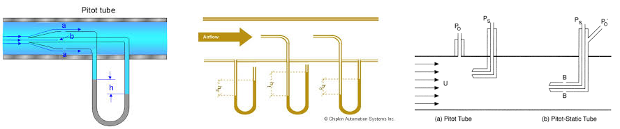
Note: Measurement of True Static Pressure is pre-requisite
Advantages:
- The classical Pitot Tube has the status of being a primary standard, if used in accordance with internationally published methods, such as British Standard BS 1042, ISO 3966, and USA 40CFR60 et al. It has a Flow Coefficient of unity (1.00), which is the ratio of actual mean velocity to measured mean velocity. Because of its small diameter, typically 6mm (1/4”) in large pipes, blockage factor errors are practically negligible.
- A further important advantage is that impact/ true static Pitots have ‘no noise’ signals and respond well to pulsatile flow and measure true (√ (mean dp). This is important for response to velocity changes on aircraft, for example, on which millions of lives depend daily !
- A badly designed Pitot generates a noisy dp, which cannot respond well to pulsatile flow. It senses mean (√ dp), which provides a lower signal than the truth. They are not allowed on aeroplanes !!
Disadvantages:
- Its 90 degree bend is not convenient for inserting into ducts and pipes, especially under pressure.
- Its small size diameter and thin wall thickness are not conducive to most industrial applications
- It generates a relatively small dp, which can lead to significant errors if a dp sensor does not have accurate low range capability
Why the Many Shapes – Multi-Impact Averaging Pitots With Circular Cross Section Insert Tubes
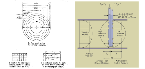
Flow specialists developed a range of more practical Pitots for heavy industrial applications in the mid – 1900s. They were capable of measuring dirty and clean liquids and gases, including steam. The first was of a robust circular cross section. It measures the differential pressure (dp) using a series of 4 +ve pressure impact pressure ports upstream and a single downstream facing –ve suction pressure port at the pipe centre line. The impact holes are dispersed in accordance with log Tchebycheff rules, to account for most of the flow volume being at the outer areas of a pipe or duct. Some manufacturers use an internal averaging tube, with a single sensing port, some do not.
The accuracy claimed was ± 1% of reading (o.r.) over a 4 : 1 range for Reynold Numbers (Re) > 50,000. However, manufacturers published tests do not appear to state Reynolds Numbers (Re) below 200,000.
Advantages:
- Creates about double the dp of a classical Pitot tube, which in the 1900s was suitable for most industrial dp cells.
- Some embody an internal averaging tube which measures an approximate average impact pressure and claimed to allow shorter straight pipe runs. Other types have dispensed with the averaging tube.
- Large pressure ports enable dirty media to be measured.
Disadvantages:
- The circular cross section creates sufficient turbulence at the -ve suction port that its signal to noise ratio is compromised
- Quantity of 4 impact pressure ports is not in accordance with ASHRAE and USA 40CFR60 Code of Federal Regulations, which states 6-impact pressure ports should be used
- The –ve suction is not a true static pressure, with errors in pressure compensation for mass flow of gas and steam
- Impact/suction Pitots do not correctly respond to pulsatile flow and measure (mean √ dp) which is lower than the true (√ mean dp). Therefore they show a lower flow rate than the true flow rate.
- Not used in the water industry, since suction signal too “noisy” and inaccurate for low flow
- Not recommended for multivariable applications (where temperature, differential pressure using true static pressure, and separate true static pressure are requisite)
- Designs with an internal averaging tube are not arranged for optimum averaging accuracy
Why the Many Shapes – Multi-Impact Averaging Pitots With Diamond Cross Section Insert Tubes
This type is basically the same as the circular Multi – Impact Averaging Pitot, except with a diamond shaped insertion tube. Some have multi-impact holes, with an internal averaging pipe. The averaging tube has a single averaging port at the pipe centerline. Others have dispensed with the averaging tube altogether, since earlier claims on reduced straight pipe lengths were not always found to be correct. The claims for straight pipe runs are, however, surprisingly still remain the same !
Other types, which have dispensed with an internal averaging sensing tube, have 4 suction pressure ports opposite each of 4 impact pressure ports. This is really an admittance that the static pressure is not being measured, since true static pressure sensing would be the same throughout the pipe, unaffected by velocity pressure or variable suction effects.
Some assert the diamond’s lower resistance to flow allows a more constant calibration factor. This is somewhat academic, since the diagram below shows only a significant variation in resistance factor (which in turn affects the Calibration Factor) occurs at Reynolds Numbers < 50,000 and are not normally encountered in actual applications.
Advantages:
- Creates about double the dp of a classical Pitot tube
- The diamond shaped cross section creates less turbulence than circular shapes and provides a less “noisy” suction pressure signal than from circular cross section types
- Large pressure ports enable dirty media to be measured
Disadvantages:
- Increased cost for special diamond-shaped extrusion
- Apparent accuracy + – 0.5% of reading for Reynolds Numbers > 200,000
- Those designs which dispense with an internal averaging tube velocity effectively measure centre pipe velocity, which at low Reynolds Numbers may be as much a 20% higher in velocity as the true mean velocity. Significant errors can result.
- Impact/suction Pitots do not correctly respond to pulsatile flow and measure (mean √ dp) which is lower than the true (√ mean dp). Therefore they show a lower flow rate than the true flow rate.
- Those designs with an internal averaging tube have not arranged it for optimum averaging accuracy (subject of a tekflo sensors patent application)
- Quantity of 4 averaging Pitot ports is not in accordance with ASHRAE and USA 40CFR60 Code of Federa Regulations, which states 6-impact pressure ports should be used
- The –ve suction is not a true static pressure, with errors in pressure compensation for mass flow of gas and steam
- Not used in the water industry, since suction signal too “noisy” and inaccurate for low flow applications
- Not recommended for multivariable applications (where temperature, differential pressure using true static pressure, and separate true static pressure are requisite)
Why the Many Shapes – Averaging Pitot with Tee Cross Section Insert Tube
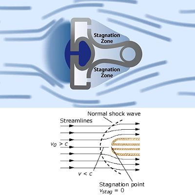
The cross sectional Tee approach is to measure dp across an upstream impact pressure slit, which extends substantially over the pipe id, and suction pressures on each downstream side of the Tee. While the Tee provides efficient boundary layer break-away, the true static pressure is not measured. A plenum for a thermocouple is also provided for multivariable sensing, such as for mass flow of gases and steam.
Advantages and Disadvantages are as with diamond shapes. The extrusion is an added high cost disadvantage, but In particular it is emphasised that a single upstream slit effectively measures center pipe velocity. At low Re Numbers, up to 20% differences in true mean velocity and center velocity are possible, resulting in serious errors (see diagram).
Claimed accuracy: ± 0.75% of reading over 10:1 range For Re >13000. Re Numbers at 13000 are not always consistent with flat profiles, which makes this statement requiring qualification.
The noisy Impact/Suction signal does not allow system to respond well to pulsatile flow, so it measures (mean √ dp). This is lower than the true (√ mean dp), resulting in negative errors.
As for foregoing Pitot types, tekflo sensors Singapore does not recommend such devices for multivariable sensing since true static pressure is not measured and center line velocity sensing is unacceptable.
Why the Many Shapes – Extruded Shape Averaging Pitot with Multi-Positive and Multi-Negative Ports
In an attempt to revert to the classical Pitot principles, with its true static pressure sensing, a specially shaped elongated extrusion averaging Pitot was developed with multiple impact ports and multiple so-called ‘static’ ports on the side. It is claimed that correct positioning of the multiple ports on the side of the special extrusion provides a true static pressure measurement. Extensive tests performed by tekflo engineers did not reveal this, and gave an unacceptable signal to noise ratio. The tests also revealed small deviations in alignment with the pipeline axis gave unacceptable errors.
Manufacturers accuracy claims:
± 1% of reading over 3 : 1 range
± 2% of reading over 5 : 1 range
± 3% of reading over10 : 1 range
No mention of minimum Reynolds numbers appear to be given and unsuitable for multivariable sensing.
Other disadvantages are as with diamond shaped Pitots, with an extra disadvantage:
The so-called ‘static pressure’ holes at the side of the extruded insertion tube are from necessity too small for use with dirty media and also provide a relatively “noisy” signal .
As with Impact/Suction systems, the noisy signal does not allow system to respond well to
pulsatile flow, so it measures (mean √ dp). This is lower than the true (√ mean dp) with –ve errors