NanoTek – The First Prevention Against Dangerous Airborne Viruses and Pollutants
Tekflo Sensors proudly announces NanoTek, having a unique technology, which provides the first prevention against dangerous airborne viruses and pollutants. NanoTek meets the USA government Environmental Protection Agency (EPA) Standard PM 2.5 for protection against dangerous airborne particulate pollutants down to 1 micron (i / 1000 mm) size.
As such, NanoTek provides the first comprehensive source of PROTECTION against the following airborne pollutants:
- Covid 19 virus and their derivatives
- Forest fire, fog, smog and airborne particulate pollutants
- Vehicle exhaust
- Influenza
- Factory airborne pollutants and airborne odours
- Asthma, conjunctivitis (pollen and hay fever}, SARS( severe acute respiratory syndrome)
PREVENTION IS CHEAPER AND BETTER THAN CURE
The World Health Organisation (WHO) asserts that 90 percent of the world’s population suffers from some sort of lung infection, which shortens life span from various pollutants entering the lungs via the nose and mouth. Common masks worn by millions of people, we assert, do not provide adequate protection against airborne particulate pollutants, which find their way to peoples lungs via the nose and mouth.
NanoTek uniquely does not, here’s why:
- NanoTek is a complete factory assembled pneumatic system, which uniquely provides a continuous clean air purge to a comfortable, close fitting mask worn over the nose and mouth. It is a lightweight and portable system, provided in a weatherproof back or front worn pack. This contains an air canister providing clean air for up to 1 hour use in an pollution affected environment. Alternatively, the system pneumatics may be assembled in an attractive portable container on wheels, which houses a heavier air canister for up to 2 hours continuous protection. The air canister is topped up as easily and quickly as pumping up a car tire.
- The NanoTek system is a master piece of bi-directional pneumatic instrumentation. It is virtually solid state, having no moving parts, such as levers, springs etc. this ensures high insensitivity to pink noise, typically such as from vehicles travelling over rough territory or from vibrating machinery. Clean air is supplied to the mask at a low purge pressure above the pressure of normal airborne pollutants, but refreshingly comfortable and fitting to the face at air velocities up or near Mach 1, the speed of sound. This in turn provides a response time of around 10 milleseconds to STOP airborne pollutants as soon as they arrive at the mask and no further.
- The NanoTek has an optional refreshing and relaxing natural Thai herb aroma unit, switched from air by the turn of a valve.
- The NanoTek mask includes 2 breather air respirators, approved to USA EPA standard PM 2.5
- The NanoTek mask is fitted with outer and inner soft, comfortable textiles. in the middle of which is an electro – static textile as an extra guard against particulate pollutants and again with the USA EPA standard PM2.5
- Amazingly, NanoTek includes airborne pollutants arriving from a breath, slight cough or sneeze or in wind gusts up to velocities of 30.8 – 38.6 km/h (i9 – 24 mph, maximum Beaufort Number 5. This is strongly advised for use by the courageous doctors and nurses in close contact with possibly infected patients
Details are provided in the NanoTek data sheet here.
NanoTek saves governments and businesses huge sums of money by obviating the need for the 2 meter distance between people rule and provides the case for no more virus scare lock downs.
PREVENTION IS CHEAPER AND BETTER THAN CURE
Further details are also available by email to Dr. Robert Batey Ph.D, Ch. Eng. UK (robert.batey@tekflosensors.com)
tekSon TS Series Low Cost Ultrasonic Water Energy Flow Measurement
tekflo sensors are proud to present their tekSon TS Series ultrasonic water energy meter, which uniquely meets EN1434 Class 1 total energy system accuracy for pipe sizes 15mm to 2000mm (1/2” – 80”) pipe diameter.
tekSon measures hot or chilled water energy by continuous sensing of the multiplication of flow rate and the differential temperature of the inlet and outlet temperature to a chiller or heat generator.
The versatile TS ultrasonic flow sensors may be clamped horizontally on the same side of the pipe on existing hot or chilled water pipes from 15mm (1/2) diameter. Alternatively, they may be inserted diagonally opposite each other into weld bosses at an angle to the centre line on existing pipes from 32mm (11/4”). A complete spool piece is also available for pipe sizes from 25mm (1”). All types have a maximum diameter of 2000mm (80”).
Twin tekSon ultrasonic sensors operate on the most accurate time of flight principle, employing 4-byte IEEE 754 floating point computation. Each sensor embodies a solid state piezo-ceramic crystal, which acts alternatively as transmitting or receiving ultrasonic pulse generators, in either V formation up to 50mm or diagonally for the larger pipes. In each case the flow rate is proportional to the time difference between the transmitted and received ultrasonic pulses.
The complete system including flow sensing, matched differential temperature sensing and the all-digital computation of energy, meets EN1434 Class 1 system accuracy of < ± 1 of reading over a 10 : 1 energy flow range and < ± 1.2% of reading over a 30 : 1 energy flow range. Each tekSon flow sensor is supplied with a customised flow Calibration Certificate traceable to USA NIST (National Institute of Standards and Technology). The temperature sensors are certified to meet a minimum differential temperature of 3º Kelvin with EN1434 Class 1 accuracy status.
Features:
- The only ultrasonic energy system meeting EN1434 Class 1 for sizes from 15 – 2000mm diameter
- tekSon flow sensors are custom calibrated with system certified accuracy traceable to USA NIST
- Independent of media density changes caused by variation in additives, such as ethylene glycol, propylene glycol, brine etc. Note: turbine flow or other small meters cannot claim this.
- Low cost. Clamp-on sensors installed on existing pipe lines have no pipe modification costs
- Suitable for metal or plastic PVC/FRP and similar pipes
- Flow and temperature sensors are submersible to IP68 and NEMA 6 P to 1 m water gauge
- Clamp-on sensors may be used for NIST traceable on-site revalidation of other energy sensors
- Matched temperature sensors certified to a minimum differential of 3º Kelvin with NIST traceability
- 3-wire Pt 100 temperature sensors suitable for minus 30 to + 160º C (minus 22 to + 320º F)
- Solid state, non- media contact flow sensors with no moving parts
- Zero pressure loss, unlike turbine type meters or Spire’s labyrinth ‘Z’ ultrasonic system
- Suitable for small air bubble entrainment and turbidity to 10000 ppm
- Continuous mean velocity sensing from zero to 10 m/s. No mechanical cut-off.
- 4-20mA and scaled pulse, isolated hi/lo relay outputs, RS485 data interface
- 3 x 4-20mA inputs for use with alternative magnetic flow sensors, pressure, level and temperature
Why tekSon Zero Pressure Drop Is Important
A requirement of EN 1434 is that manufacturers must specify pressure drop across their flow sensor. Pressure drop can affect accuracy of an energy flow metering system since it increases the pump energy consumption. If the pump cannot compensate for the pressure drop, which increases with the square of the flow rate, the chilled or hot water flow may easily fall below design requirements. This in turn may cause a reduction in a building’s heating or cooling capacity and reduction in energy efficiency of the heating or cooling appliance, especially if it uses a heat pump.
tekSon plays an important role in alleviating the above problem caused by pressure drop. Consider competitive flow metering pressure drops at normal flow rates with tekSon:
| Company and Flow Sensor Type | Pressure Drop At Normal Flow Rate |
|---|---|
| Onicon Insertion Turbine | 0.1 bar (> 150mm pipe), 0.2 bar (< 150mm pipes) |
| Signet Paddle Wheel | 0.1 bar (> 150mm pipe), 0.2 bar (< 150mm pipes) |
| Sprire Labyrinth Z Ultrasonic | 0.15 – 0.2 bar small pipes onlyCompact or remote Battery powered < +- 1% of reading |
| Landis & Gyr Ultrasonic | 0.15 – 0.2 bar small pipes only |
| tekSon Ulrasonic | Zero at max flow 15 – 2000mm pipes |
About EN1434
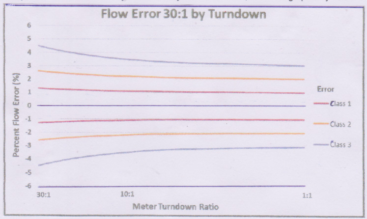
EN1434 is a European Standard specifying the combined accuracy of the flow sensor, the pair of temperature sensors and the electronics in which the calculation is performed, displayed and transmitted. Cooling water and hot water energy metering systems are classifies by the combined system accuracy in terms of Class 1, 2, or 3 as follows:
Ei = ± ( 1 + 0.01qp/q ) but not > 3.5%………Class 1
Where Ei = % uncertainty in energy measurement
qp = highest flow rate at which the flow sensor continuously function
q = actual operating flow rate
Note: Flow sensors with moving parts should guarantee the ‘continuous function life’
Similarly, Ei = ± ( 2 + 0.02qp/q ) but not > 5%………Class 2
and Ei = ± ( 3 + 0.05qp/q ) but not > 5%………Class 3
To this EN1434 specifies that the temperature error of the temperature sensor pair is arithmetically added to the combined errors above, not root of the sum of the squares):
Et = ± ( 0.5 + 3ΔǾmin/ΔǾ )
Where Et = % uncertainty in the differential temperature sensing
ΔǾmin = minimum temperature difference of temperature sensors
ΔǾ = actual operating temperature difference
tekSon temperature sensors are accurately matched to meet a minimum differential temperature of 3º Kelvin to provide a total arithmetic system accuracy to meet EN1434, as shown graphically below:
Using tekMass Thermal Mass Flow Sensors to Cut Costs and Improve the Environment
How tekMass Operates
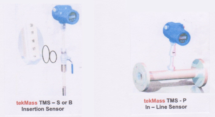
tekMass embodies 2 high stability thermal sensors, either for insertion into a pipe or duct, under pressure if necessary. Alternatively, it may be supplied as an in-line sensor, complete with spool piece and process flanged connections. They are only suitable for gas flow, not including steam.
One sensor is heated and the other is a reference. The reference sensor resistance is accurately maintained and the power required to provide a constant temperature between the heated sensor and the reference sensor is a measurement of the mass flow of the gas flowing past the 2 sensors.
tekMass is normally calibrated on air, or the application gas, against a pressure and temperature compensated sonic nozzle to ISO9300 with an accuracy of 0.2% of reading. This is an internationally recognized primary standard.
On some occasions, for example exotic or mixed gases, the calibrated air mass flow can be corrected by determining the square root of the product of the thermal conductivity and density of the particular application gas. A customized NIST traceable Calibration Certificate is provided for each tekMass, expressed in either volumetric flow corrected to normal NTP conditions or in mass flow units.
The overall accuracy of tekMass, including corrections where necessary, and the sonic nozzle, is < ± 1% of reading, or ± 0.5% of full scale, whichever is the greater.
Why Use tekMass – Some Useful Facts
It is obvious why tekMass should play an enormous role in both money saving and in protection of the environment. Please consider:
+ A I kg mass of methane gas has 28 times greater influence on global warming than 1 kg of carbon dioxide, but both play a major role in global warming. (Energy Institute of Haas, University of California, Berkeley)
+ Methane gas leaking from natural gas systems represents 2.8% of the total energy related world’s greenhouse gas emissions. (USA Environmental Protection Agency)
+ The value of natural gas lost through pipe leakage is US $300 million per annum using 1996 average costs. Applying a “social cost” of US $37 per normal metric USA ton of carbon dioxide, the cost of leaked gas exceeds US $2 billion per annum. (USA Department of Environment)
+ It is incumbent on utilities world-wide involved with biogas, methane, carbon dioxide and natural gas to accurately monitor both ends of pipeline carriers to determine how much leakage occurs and to use the results to ensure minimal or zero leakage. With tekMass such leakage is detected at typically within 1% NIST traceable accuracy. This 1 % applied to
US $300 million natural gas lost per year represents an annual saving of US 297 million.
+ Large savings can be demonstrated using simple compressed air applications.
Example: A typical compressor uses 50kWh and produces 480 nm3/h air.
Therefore, 1 nm3/h consumes 50 / 480 = 0.104 kWh
Assume average electricity costs are US $0.137 / kWh
The cost of electricity = 0.104 kWh / nm3 x US $0.137 = US $0.0143 / nm3
To arrive at a more truthful amount, the compressor industry estimates an average 70% due to the compressor, the total being the additional costs of maintenance, installation, etc.
Therefore a more accurate cost would be US $0.0143 / 0.7 = US $0.0204/nm3
Taking a typical example of a 100mm pipe delivering 1000 nm3/h, the cost would be
US $0.0204 x 1000 nm3/h = US $20.4 / h = US $178700 per year.
The USA Department of Energy estimates most compressed air plants are operating at 10% leakage. From the figure above this represents a loss of US $17870 per annum
With serious leak remediation and using a tekMass TMS to show leakage to a known and traceable 1% represents a saving of US $178700 – US $1787 = US $176900 per annum.
Presented by: Dr Robert Batey
For further details consult robert.batey@tekflosensors.com and www.tekflosensors.com
Making Sure Your tekMass thermal Mass Flow Sensor Operates Efficiently
The patented tekMass TMS Series is designed for bi-directional mass or NTP corrected volumetric flow measurement of pure or mixed gases.
tekMass has the largest flow ranges available from 0.35 kg/h to over 12 million kg/h (1.2 lb/h to > 26 million lb/h). It is accurate to < ± 1% of reading, with traceability to USA NIST and other international standards. However, as with all flow sensors, in order to achieve such performance, users should be aware of the principle of operation, some of the common challenges and how to avoid them.
How tekMass Operates
tekMass embodies 2 high stability thermal sensors, either for insertion into a pipe or duct, under pressure if necessary. Alternatively, it may be supplied as an in-line sensor, complete with spool piece and process flanged connections.
One sensor is heated and the other is a reference. The reference sensor resistance is accurately maintained and the power required to provide a constant temperature between the heated sensor and the reference sensor is a measurement of the mass flow of the gas flowing past the 2 sensors.
tekMass is normally calibrated on air, or the application gas, against an internationally recognized primary standard. On some occasions, for example exotic or mixed gases, the calibrated air mass flow can be corrected by determining the square root of the product of the thermal conductivity and density of the particular application gas. A customized NIST traceable Calibration Certificate is provided for each tekMass, expressed in either volumetric flow corrected to normal NTP conditions or in mass flow units.
Some Important Challenges
• Sizing the tekMass
It is important to state the type of gas such that the thermal conductivity and specific heat can be determined, as well as the operational density (temperature and pressure range).
The tekMass data sheet provides recommended flow rates based on air at NTP (20º C, 1.013 bar absolute). As the thermal conductivity and of a gas increases then the tekMass signal increases by square root law over the tables on air flow range at NTP. That means the equivalent air flow range at NTP is less. The specific heat also plays a non-linear role in determination of equivalent air flow at NTP
As a gas pressure increases, the gas molecules become packed more closely together, meaning its density will increase. Accordingly, the tekMass signal increases also by square root law over the tables on air flow range at NTP. Again, the equivalent air flow range at NTP is less
To avoid the resultant decreased sensitivity caused by variation in specific heat, higher thermal conductivity of gases and/or higher gas pressures, flow rates or their calculated equivalents greater than those stated in the tekMass data sheet are not recommended. Generally, it is also not recommended to use thermal gas flow sensors greater than 10 bar g (145 psig). In all these cases a tekVorx vortex sensor or tekProbe multivariable averaging Pitot should be used. Consult tekflo sensors for expert advice.
• Moisture in the Gas
Condensed moisture in the gas contacting the thermal sensors will suddenly result in increased thermal conductivity. The raw signal will become ‘noisy’ with increased spikes, resulting in decreased accuracy and repeatability. Damping the signal does not provide an accurate result, since the noisy, spikey signal is very irregular. Damping the signal does not result in accurate averaging.
One way of obviating the problem requires installing a moisture separator in the pipeline upstream of the tekMass. The straight pipe runs should be a minimum 15 diameters upstream after the moisture separator and 5 downstream before a bend. When the moisture laden gas enters the relatively large separator there is a localized reduction in its velocity, besides a change in direction. The moisture falls to the bottom of the separator tank, leaving the resultant dry gas to flow upwards and out.
A less expensive and simper approach is to place the tekMass at typically 45 degrees from vertical in a horizontal pipe. The condensed moisture then drops away from the tekMass.
Should there be extreme amounts of moisture in the gas, a tekVorx vortex sensor or tekProbe multivariable averaging Pitot should be considered. Consult tekflo sensors for expert advice.
• Solids Build-Up
In most cases, when solids build on the thermal sensors the effect is to reduce the thermal conductivity. This causes the tekMass to read lower and reduce response time. There are some solids of high thermal conductivity which have the opposite effect, but these are in a significant minority.
The easiest solution is to use a retractable insertion tekMass, complete with locking gland and ball valve, through which the tekMass may be withdrawn under pressure for periodical cleaning.
Should there be extreme amounts of solids in the gas, a tekVorx vortex sensor or tekProbe multivariable averaging Pitot should be considered. Consult tekflo sensors for expert advice.
• On-Site Calibration Verification
tekMass is equipped with advanced calibration verification, which is on-site traceable to USA NIST and other international standards, When the tekMass microprocessor is turned on a self-check analysis is performed automatically. This calibration check may also be performed when desired.
If any change to the original calibration occurs, for whatever reason, a self-check interface will be displayed for 1 – 2 seconds. A display will change from OK to ERR, meaning error. The menu can then be programmed such that a display showing which parameter is at fault or not. The checks are for the Internal Clock, Memorizer, Power Supply, Analog to Digital Converter, Parameter Fault, Sensor Fault. A tick √ is indicated when a check is satisfactory, a X is indicated when a check is unsatisfactory and requires appropriate action in accordance with the tekMass Instruction Manual.
• Irregular Velocity Profiles
The low density of gases, compared to liquids, often means taking special precautions to provide regular velocity profiles and to prevent rotational and even tumbling movements inside a pipe or duct. If these precautions are not taken, inaccuracy and poor repeatability ensues.
Attention is drawn to the tekMass Instruction Manual and data sheet, which provides minimum straight lengths of pipe upstream and downstream of tekMass. If the straight lengths of pipe or duct are not available, then tekMass can be supplied with a flow conditioner, which allows significantly less straight lengths.
Should there still be not sufficient straight lengths, then a tekProbe PR7 for circular pipes, or tekProbe PR8 for rectangular/square ducts should be considered. These have integral flow straighteners with multiple averaging Pitots and require only 5 – 8 diameters or equivalent diameters upstream and 2 downstream. See the appropriate data sheets or consult tekflo sensors for expert advice.
For further details consult robert.batey@tekflosensors.com and www.tekflosensors.com
tekMag Intelligent Magnetic Flow Sensors – Not Just Another Magmeter
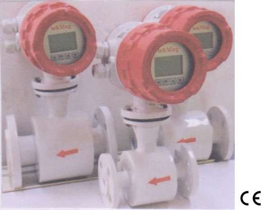
The comprehensive range of tekMag magnetic flow sensors operate on the Principle of Faraday’s Law, which states when a conductor moves through a permanent or an electro-magnetic field B, a signal voltage U is generated, whose amplitude is proportional to the mean velocity v of the conductor. The conductor is the measured media flowing through the magnetic flow sensor. The generated voltage is measured across 2 electrodes situated diametrically opposite each other in the walls of an obstruction free flow tube, diameter d. The flow tube and electrodes are insulated from each other by a thick, non-microporous liner of various materials. The magnetic field is normally generated by coils, whose axes are at 90º to the electrodes All tekMags are bi-directional.
From Faraday’s Law: U = k. B. v. d
Initiating a step further, engineers and scientists at tekflo sensors pioneered an advanced solution to signal quality. They were the first to prove that the signal to media noise ratio was inherently proportional to the multiplication of the magnetizing current and the square root of the cube of the exciter frequency for a given electrically pulsed coil. This further resulted in a fast time constant, which in turn allowed true mathematical averaging of irregular pulsatile or noisy flow.
The quality of the signal, or more precisely, the signal to media noise ratio, is a dimensionless function of:
Signal Quality Factor = Im . t . P. f1.5 . L0.5
Where Im = magnetizing current t = signal evaluation period
P = the excitation polarization, where P =1 for uni-polar and P = 2 for bi-polar
f = the exciter frequency L = the coil inductance, normally measured in Henrys
The Practical tekMag Difference
1) A typical normal 150mm (6”) diameter pulsed DC magnetic flow sensor has a magnetizing current Im of 0.1 Amps peak to peak, an evaluation time of 20ms, a bi-polar excitation of P = 2, an exciter frequency of 4 Hz and a coil inductance of 0.5 Henry.
Normal Signal Quality Factor = 0.1 x 20 x 2 x 41.5 x 0.5 0.5 = 181
2) A typical tekMag 150mm (6”) high powered pulsed DC magnetic flow sensor has a magnetizing current Im of 0.3 Amps peak to peak, an evaluation time of 20ms, a bi-polar excitation of P = 2, an exciter frequency of 12 Hz and a coil inductance of 0.5 Henry.
tekMag Signal Quality Factor = 0.3 x 20 x 2 x 121.5 x 0.50.5 = 353
This demonstrates that tekMag, through unique design, has a Signal Quality Factor typically 2 times greater than normal pulsed DC magnetic flow sensors.
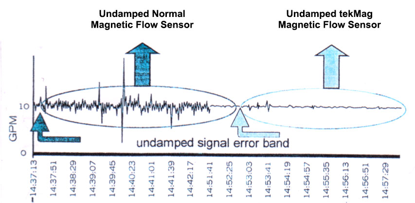
Media such as greasy raw sewage, paper pulp, slurries or media causing calcium carbide coatings create piezo (impact) or tribo (frictional) electrical noise at the electrodes of all magmeters. These cannot be simply damped out, as is often attempted, since the noise is irregular in frequency and magnitude. A true average is not accomplished, causing puzzling and costly errors.
This problem does not exist with tekMags. They have the highest possible magnetizing current at the highest practical frequency, combined with low power consumption, at probably the lowest prices on the market. This allows for the first time a truly economical method to guarantee the measurement of problem media on-site, without loss of accuracy and based on a USA NIST traceable customized calibration.
tekMag Features Summary
- tekMag technology offers the highest possible signal : media noise ratio
- Suitable for permanent coatings of sewage grease
- High accuracy to ± 0.25% of reading > 0.1 m/s (0.3 fps)
- Resolution to 1000th of range
- Calibration Certificates with traceability to USA NIST and other international standards
- Quality Assurance to ISO 9001
- Guaranteed operation to customized specification straight from the packing crate
- Range of sizes 2 – 2000mm (0.08” – 80”)
- Meets European EMC Conformity Standards to EN 61326 – 1 for industrial locations
- Meets European Pressure Equipment Directive – Sound Engineering Practice
For further details consult robert.batey@tekflosensors.com and www.tekflosensors.com
Understanding the True Cost of Steam and How tekVorx Vortex Sensors Significantly Reduces Them
The Unloaded Cost of Producing Steam
The unloaded cost of steam production considers the fuel cost, the steam enthalpy (BTU/lb), the boiler feedwater enthalpy and boiler efficiency. The boiler efficiency considerations are provided in ASME PTC 4.1, which is available free in public domain sources, such as Google.
The equation to calculate the unloaded steam cost is:
Sc = Unloaded Steam cost
Fc = Fuel cost
Es = Steam enthalpy (BTU/lb)
Eb = Boiler feed water enthalpy (BTU/lb)
Ƞ = Boiler efficiency is 80% (ASME PTC 4.1)
Example:
Calculate the unloaded steam cost where the fuel cost (averaged over typically 1 year) is US $9.50/million BTUs, the steam enthalpy is 1190 BTU/lb, the boiler feed water enthalpy is 208 BTU/lb.
Sc = US $9.50 (1190 – 208) / 1000 x 0.80 = US $11.67 per 1,000 lb or US $25.65 per 1,000 kg
The Loaded Cost of Producing Steam
The loaded cost is the preferred method of plant accountability and involves serious management determination. Loaded costs include those of electrical power, chemical, water use and waste/sewage disposal, as well as Governmental emission payments, management, operational, and new projects. It can be shown by most companies that the loaded cost can be 50 % to 100% higher than the unloaded costs of steam production.
By way of example we shall assume a 75% loaded cost over the unloaded cost. Now the true cost of raising steam would be US $11.67 x 1.75 = US $20.42 per 1000 lb or US $44.88 per 1000kg
How Accurate, Long Term, Low Cost tekVorx can Help
If we take a typical 4” (100mm) pipe line at 10 bar (145 psig) with a flow range typically 1150 – 28,900 lb/h and a normal flow rate of, say, 20000 lb/h. With a loaded cost of US $20.42 per 1000 lb, the cost at normal flow rates would be US $20.42 (20,000 /1000) = US $408.4 per hour = $3,529,000 per year.
One of the most common flow meters for measuring steam flow is the sharp edged orifice plate, across which the differential pressure (dp) is measured and the square root law of flow rate to dp is extracted. This has a typical range of not more than 4 : 1, and an average system accuracy based over 1 year of ± 3% of full scale. This error accounts for the erosion of the sharp edge due to abrasive steam flow. Since the accuracy is based on “full scale,” at normal flow the actual accuracy would more like ± 3.5% of reading. In loaded cost terms, this would represent a flow reading ambiguity of ± 3.5/100 x $3,529,000 = ±US $ 124,000 per year.
The tekVorx vortex flow sensor manufactured by tekflo sensors has a performance insensitive to the most abrasive of steam. Any erosion caused on its internal bluff body is negligible . The typical accuracy under site conditions is ± 1% of reading over a 25 : 1 turndown and is certified traceable to the USA National Institute of Standards and Technology (NIST) and other international standards. It is custom calibrated to our customers required flow range, making it a No Dispute sensor.
Using the example above the ambiguity of reading would be reduced to US $35,300 per year.
With the ambiguity of loaded cost being reduced by 3.5 times, the tekVorx provides plant management with significant scope to REDUCE loaded costs of steam raising, with a “No Dispute” NIST traceable calibration over a typical 25 : 1 flow turndown to their credit.
For comprehensive details on the tekVorx vortex flow sensor please see the attached data sheet. Request a quote through our exclusive Authorized Distributor, or through tekflo sensors. You will be pleasantly surprised at how tekflo sensors has achieved such high Singapore quality at probably the lowest price available.
For questions relating to the above and other flow applications, please e mail:
Dr Robert Batey
robert.batey@tekflosensors.com
Director of Engineering and Marketing